
Industry Insights
Causes of Unstable 224G High-Speed Cable Transmission: Materials, Structure, and Connector Optimization
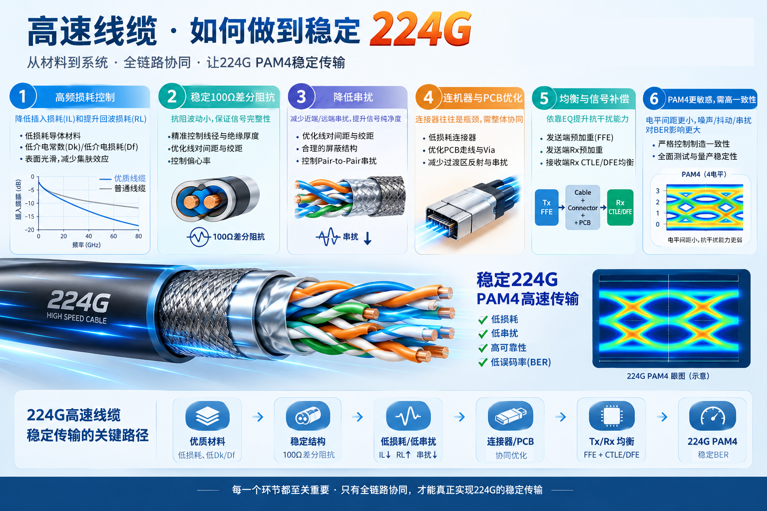
For a 224G PAM4 high-speed cable to deliver stable performance, improving the cable alone is not enough. Materials, physical structure, impedance, loss, crosstalk, connectors, equalization, and manufacturing consistency must all be controlled as an integrated system.
Key Factors for Stable 224G Transmission
Control High-Frequency Loss
A 224G PAM4 signal typically operates at approximately 112 GBd, corresponding to a Nyquist frequency of about 56 GHz, depending on the protocol and encoding scheme.
At high frequencies, skin effect and dielectric loss increase significantly. Conductors should therefore have low surface roughness, while both conductor and dielectric materials should exhibit low loss. The dielectric constant and dissipation factor—Dk and Df—should be minimized wherever possible.
Particular attention must be paid to insertion loss (IL) and return loss (RL).
Maintain Highly Stable Impedance
The typical target is a 100 Ω differential impedance.
An average value of 100 Ω is not sufficient; impedance variation must remain low across the entire cable length. Conductor diameter, insulation thickness, pair spacing, twist pitch, and eccentricity can all affect impedance stability.
Reduce Crosstalk
224G transmission is highly sensitive to both near-end and far-end crosstalk. Key measures include:
- Optimizing pair spacing
- Controlling twist pitch
- Improving the shielding structure
- Reducing pair-to-pair crosstalk
- Controlling crosstalk in connector and PCB transition regions
Treat Connectors as Part of the Complete Channel
The connector is often the performance bottleneck. A cable may meet its standalone specifications, but the complete channel can become unstable once it includes:
Chip → PCB → Connector → Cable
For 224G applications, connectors, PCB traces, vias, pads, and other transition structures must therefore be evaluated together through signal integrity (SI) simulation.
Use Equalization and Signal Compensation
224G PAM4 transmission cannot rely on a theoretically lossless cable alone. A practical system generally follows this signal chain:
Tx FFE → Cable → Connector → PCB → Rx CTLE/DFE
Transmitter pre-emphasis and receiver equalization compensate for channel loss and distortion during high-speed transmission.
Manage PAM4’s Greater Sensitivity to Noise
NRZ uses two signal levels, while PAM4 uses four. Because the spacing between PAM4 levels is smaller, the effects of the following impairments on bit error rate are significantly amplified:
- Noise
- Jitter
- Crosstalk
- Reflections
- Inter-symbol interference (ISI)
Ensure Manufacturing Consistency
Stable 224G performance ultimately depends on maintaining tight and repeatable control over materials, dimensions, structural parameters, assembly processes, and electrical performance throughout volume production.
One of the greatest challenges in 224G cable manufacturing is not producing a single cable capable of supporting 224G transmission, but ensuring that every cable produced in volume delivers stable 224G performance.
Key parameters that must be tightly controlled include:
- Conductor diameter
- Insulation outer diameter
- Conductor eccentricity
- Twist pitch
- Pair spacing
- Shielding structure
- Impedance
- Insertion loss and return loss (IL/RL)
- Crosstalk
- Length consistency
The performance relationship of a 224G high-speed cable can be summarized as follows:
Low-Loss Materials
↓
Stable 100 Ω Differential Structure
↓
Low Insertion Loss + Low Return Loss
↓
Low Crosstalk
↓
Optimized Connectors and PCBs
↓
Tx/Rx Equalization
↓
Stable BER Performance at 224G PAM4
A significant deterioration at any stage can rapidly degrade the final eye diagram.